 lab@motestainstruments.com | Civil and Mechanical Engineering Lab Equipments India China

Code: ETOPM10051
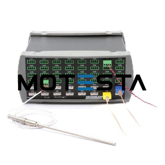
Data Acquisition system.
Data acquisition system with minimally the following specifications: - 5 Analog inputs
2 Analog voltage inputs A and B on 4-mm safety sockets (electrically isolated)
- Resolution: 12 bits
- Measuring ranges: ±0.1/±0.3/±1/±3/±10/±30/±100/±250 V
- Measurement error: ± 1 % plus 0.5 % of range end value
- Input resistance: 1 MΩ
Scanning rate: up to 1 MHz per input
- Amount of measured values: nearly unlimited (dependent on PC) up to 10,000 values/s, at higher measuring rate max. 200,000 values
- Pre trigger: up to 50,000 values per input
- 1 Analog current input A on 4-mm safety sockets (alternatively to voltage input A)
- Measuring ranges: ±0.03/±0.1/±0.3/±1/±3 A
- Measurement error: voltage error plus 1 %
- Input resistance: < 0.5 Ω
- Scanning rate: up to 1 MHz per input
- See voltage inputs for further data
- 2 Analog inputs at sensor box connector sites A and B
- Measuring ranges: ±0.003/±0.01/±0.03/±0.1/±0.3/±1 V
- Input resistance: 10 kΩ
- Scanning rate: up to 500 kHz per input
- See voltage inputs for further data
- 4 Timer inputs with 32-bit counters at sensor box sites A and B (e.g. for GM box, timer box or Timer S)
- Counting frequency: max. 1 MHz
- Time resolution: 20 ns
- 5 LED status indicators for analog inputs and USB-port
- Colours: red and green, according to status
- Light intensity: adjustable
- 1 Changeover relay (switching indication via LED)
- Range: max. 250 V/2 A
- 1 Analog output (LED switching state indicator, e.g. for holding magnet or supplying experiment)
- Variable voltage range: max. 16 V/200 mA (load ≥ 80 Ω)
- 12 Digital inputs (TTL) on sensor box sites A and B (at present only used for automatic sensor box detection)
- 6 Digital outputs (TTL) on sensor box sites A and B (at present only used for automatic switching of a sensor box measuring range)
- 1 USB-port for connection to a computer
- 1 data bus for connecting additional modules
- Dimensions (WxHxD): 115 mm x 295 mm x 45 mm
- Weight: 1.0 kg
- Supports up to 8 cascadable data acquisition systems at a USB-port respectively
- "Plug and play" enabled for easy use: the software automatically detects the connected module and sensor boxes and displays these graphically, inputs and outputs are activated simply by pointing and clicking and typical experiment parameters are automatically loaded (depending on the connected sensor box)
- Measurement data can be displayed in the form of analog/digital instruments, tables and/or diagrams (also simultaneously, with user-definable axis assignment)
- Measured values can be recorded manually (at keystroke) or automatically (choice of time interval, measured time, lead time, trigger or additional measurement condition)
- Powerful evaluation functions including various fits (straight line, parabola, hyperbola, exponential function, free fitting), integrals, diagram labeling, calculation of user-definable formulas, differentiation, integration, Fourier transforms
- Convenient exporting of measurement data and diagrams via the ' clipboard
- "Logbook" function lets you briefly document other experiment information in the experiment file
- Free updates and demo version available through the internet
- PC Requirements: Windows XP or superior, free USB-port (USB apparatus)