 lab@motestainstruments.com | Civil and Mechanical Engineering Lab Equipments India China

Code: SOML0055
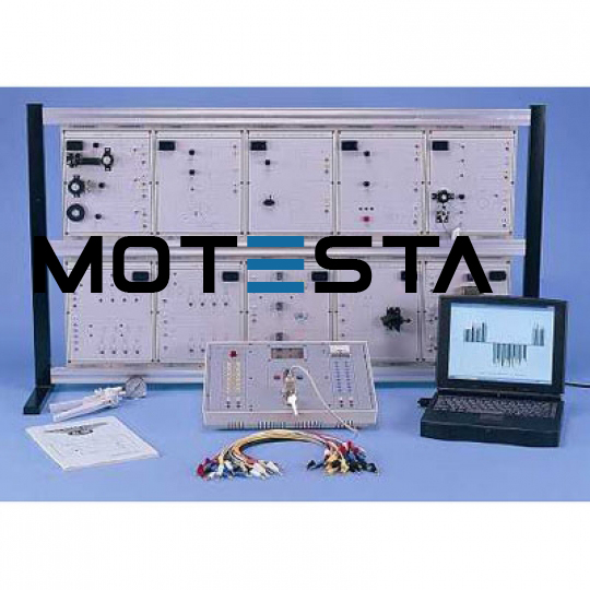
Interactive Computerized Automotive system.
The whole system has to be modularized to provide electronic and automotive courses with step-by-step experiments on technological educational training.
All theoretical, experimental and practical leaning procedures are supported by a personal computer assisted supervision and dedicated software.
The system has to simulate the operation of fuel injection system, ignition system, and the control of exhaust gas, etc. Experiments include the sensors characteristic and operation of various sensors and actuators monitored by microprocessor on the main unit.
Features
• The program should enable computer interface monitor control
• Data of fuel injection, ignition and exhaust gas should be acquired and monitored by computer.
• Able to trouble-shooting simulation function
• Switch-off input output function when trouble-shooting is made
Approx. Specifications
Main Unit
1. Power Supply Unit - Fixed DC power supply
(1) Output voltage : +5V, ±12V
(2) Max. output current: +5V/2A, +12V/2A
(3) With output overload protection
2. Computer Interface port: 9pin sub connector
3. CPU:- Single-chip processor: 89C51
4. Display
(1) LCD graphic display: 64x 128
• With back-light
• Synchronously display following values:- NE, PHO, HALL, MAF, MAT, MAP, TPS, CTS, VSS, IPW
(2) Analog meter - Oxygen’s meter
5. Selectors
(1) Select: NE, PHO, HALL
(2) Mode : Fuel injector select:- • Sync. • Non-sync. • Sequence
6. Input Signals
NE, PHO, HALL, VAF, MAT, F/C, MAF, MAP, TPS, CTS, 02,
PIN, A/C, PSPS, VSS, 3GR
7. Output Signals
(1) INJ1, INJ2, INJ3, INJ4, SPK1, SPK2, SPK3, SPK4, FANC, F/C, ACC, IAC1, IAC2, IAC3, IAC4, TCC, CCP, EGRV
(2) Check engine lamp
Experiment Modules
1. Circuits symbols, blocks and components printed on the surface of each module
2. Modules secured in plastic housing, dimension: 297x226x60mm
3. With cabinet for all modules easy storage facilities
4. Comprehensive experiment manuals
5. All modules equipped with 4/8 bit DIP switch for fault simulation
List of Modules
• Crankshaft Position Sensor
• Air-Flow Sensor (Vane Type)
• Air-Flow Sensor(Hot-Line) & Manifold Absolute Pressure Sensor
• TPS, CTS & O2 Sensor
• PIN, A/C, PSPS Switch & Vehicle Speed Sensor
• Fuel injectors/Spark Plugs
• Ignition System
• Cooling Fan & Fuel Pump &AC Compressor Relays
• Idle Air Control Valve
• TCC & CCP & EGRV Solenoid
List of Experiments
1. Crankshaft Position Sensor
(1 Pick-up sensor
(2) Photo interrupt sensor
(3) Hall IC sensor
2. Air-Flow Sensor (Vane Type)
(1) Output voltage : 0.2V-3.5V
(2) Thermal resistor MAT output: 2.3V-2.7V
(3) Fan control : F/C switch
3. Air- Flow Sensor (Hot- Line) & Manifold Absolute pressure Sensor
• Hot-Line Experiment Output voltage :- 1.0V-3.5V
• Manifold Absolute Pressure Sensor Experiment
4. TPS, CTS & 02 Sensor
• TPS Experiment
(1) Output voltage: 0.5V - 4.5V CTS experiment
(2) Voltage level : 4.5V/-40°C, 2.3V/20°C, 0.5V/108°C
• O2 Sensor Experiment
(1) Normal : 0.1 - 1.0V swing
(2) Rich : 0.6 - 1.0V swing
(3) Lean : 0.1 - 0.3V swing
5. PIN, A/C, PSPS Switch & Vehicle Speed Sensor
(1) PIN switch : Park-neutral switch
(2) A/C switch : Air-condition switch
(3) PSPS switch : Power steering pressure switch
(4) Speed sensor: Speed adjustable & 3GR switch
6. Fuel Injectors/Spark Plugs
• Fuel Injectors Experiment
(1) Static load : 180
(2) Normal rotation speed 800 rpm, max. rotation speed 3600 rpm
(3) Sequence changeable
(4) Fuel injectors LED display
• Spark Plugs Experiment LED display
7. Ignition System
• Ignition System Experiment
(1) Static load : 20
(2) LED display
• Ignition System Experiment
(1) Static load :10
(2) LED display
8. Cooling Fan & Fuel Pump & AC Compressor Relays
• Cooling Fan Relay Experiment
(1) Control signal: FANC
(2) DC 12V motor
(3) Operational conditions: - A/C signal ON or CTS signal at 108°C or under 108°C
• Fuel Pump Relay Experiment
(1) Control signal : F/C
(2) DC 12V motor
(3) Operational conditions: - Air-Flow F/C signal ON and with rotation speed
• AC Compressor Relay Experiment
(1) Control signal : ACC
(2) DC 12V motor
(3) Operational conditions: A/C signal ON
9. Idle Air Control Valve
(1) Control signal : IAC1, IAC2, IAC3, IAC4
(2) Step motor
(3) Operational conditions:- PIN, A/C, PSPS signal ON
10. TCC, CCP, EGRV Solenoid
• Torque Converter Clutch
(1) Control signal: TCC
(2) DC 12V solenoid
(3) Operational conditions:- VSS signal is over 40KM and 3GR switch ON
• Carbon Canister Purge Valve
(1) Control signal: CCP
(2) DC 12V solenoid
(3) Operational conditions:
c-1 rpm is over 1200
c-2 CTS is over 65°C
c-3 TPS is 1.0 - 2.5
• Exhaust Gas Recirculation Valve
(1) Control signal: EGRV
(2) DC 12V solenoid
(3) Operational conditions:
c-1 rpm is over 1200
c-2 CTS is over 65°C
c-3 TPS at 1.0 - 2.5
c-4 MAP at 1.0 - 1.5
• When above four conditions simultaneously exist, EGRV will be turned ON
Accessories
1. Connector leads, 4mm-4mm : 1 set
2. User's guide & experiment manual
3. Power cord
Storage cabinet: 2