 lab@motestainstruments.com | Civil and Mechanical Engineering Lab Equipments India China

Code: Civil-MCE-0064
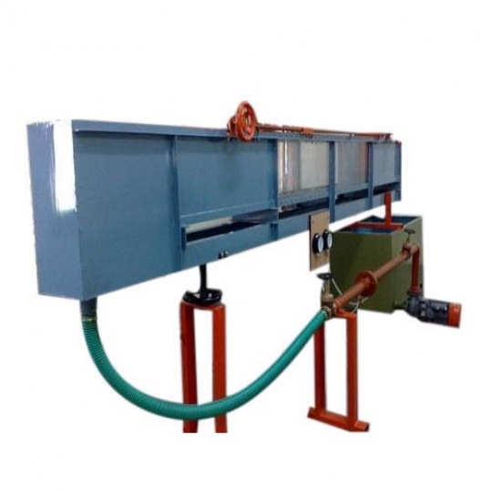
SEDIMENT FLOW CHANNEL, 600 mm Wide.
GENERAL DESCRIPTION
The channel is designed for studying the sediment transport and bed forms as well as flow phenomena without sediment. It is to be used with optional accessories and models.
Under Frame
The channel bed rests on twin beam under frame which ensures static loading deflections are kept to a minimum. The length of the beam is about 6 m Each section is shipped with glass side walls. This simplifies site installation as there are less joints and is easier to ensure straight side walls throughout the length. To ensure minimum deflection, the beam base frame of 18 m is supported by a fulcrum at the middle and adjustable height support at both upstream and downstream ends. The number of supports is more for 30 m channel length.
Slope Adjustment
Each adjustable height support uses twin screws and with a system of worm and wheel gear boxes and miter gears which are intern driven by a motor. A slope scale is provided at one end of the flume.
Channel Bed
The channel bed is made of stainless steel with twin screw holes of equal distance along the channel length to hold accessories or models to the flume bed when used as a normal tilting flow channel. These holes can also be used for pressure tapping points to measure pressure loss along the channel length.
Side Walls
For safety reasons, the side walls are made of tempered glass. The walls are supported at interval by brackets with screws for vertical position adjustment.
Instrument Carriage
Top rails made of stainless steel tubes are attached to the top angle on each wall of the channel. Screws supporting the rails can be adjusted to ensure uniform height and in a straight line. A scale graduated in mm. is attached along the full length of one top angle of the walls. The instrument carriage is manually operated.
Head Tank
The head tank is made of stainless steel and its sides and bottom are curved to ensure smooth flow into the channel. Perforated plates are also provided in the head tank to further smoothen the flow.
Sediment Feeder
The channel bed may be filled by a sediment feeder with a slope stopper upstream and another one just before sediment trap at the downstream end of the channel. Feeding is by a screw.
Sediment Trap
A sediment trap is provided at the down stream end of the channel. The trapped sediment can be discharged by a bottom value. The trap is covered when used as a normal flow channel.
Storage Tank
An underground concrete storage tank is recommended as standard. This tank is to be built by the user. However, above ground tank is available at additional cost. Walkway A steel walkway with a checker plate floor and side rails is provided on one side of the flume for ease of model installation and flow observations. Circulating Pump The pump is ceramic coated to minimize wear by sediment abrasion. A mechanical seal is used. A geared butterfly valve is provided to control accurate rate of flow.
Flow measurement
A flow digital display is used. In the case of an underground storage tank, a measuring tank with a calibrated weir is available as an option. The flow rate is controlled by a geared butterfly valve. Model and Accessories In the case of no sediment, the channel may be used as a normal tilting flow channel. All accessories and models have side seals to ensure no water seep or leak through the sides of the models. A wide variety of models and accessories are available as an option.
TYPICAL EXPERIMENTS
| As Sediment Channel : | As Tilting Flow Channel : | |||||||
| . Fixed smooth bed flow. | . Flow measurement. | |||||||
| . Flow over mobile sand bed. | . Hydraulic jump. | |||||||
| . Flow structures. | . Analysis of model structures. | |||||||
| . Local scour. | . Gauging structures. | |||||||
| . Mechanics of sediment transport. | . Velocity profile. | |||||||
| . Bed form hysteresis. | . Continuity and energy equations. | |||||||
| . Depositionary features and fancies. | . Similarity laws. | |||||||
| . Computational work. | . Roughened bed characteristics. | |||||||
| . Flow over fixed gravel bed. | . Surge propagation. | |||||||
TECHNICAL DATA
| Channel cross section | : 600 mm wide, 700 mm high and 12 m or 18 m long or as required. | |||||||
| Channel length | : 18 m (Optional : 12 m.) | |||||||
| Tilting adjustment | : -0.5 to 2% | |||||||
| Side walls | : Tempered glass. | |||||||
| Channel bed | : Stainless steel. | |||||||
| Sediment feeder | : Motorized. | |||||||
| Sediment trap | : Stainless steel with cover and sediment recovery system. | |||||||
| Storage tank | : Underground tank to be provided by user. Aboveground tank is optional. | |||||||
| Sluice gate | : Stainless steel, rack and pinion type, built-in at down stream end of flume. | |||||||
| Flow measurement | : Flow digital display. | |||||||
| Instrument trolley | : Manually operated. | |||||||
| Power supply | : 380 V, 3 Ph, 50 Hz. Other power supply is available on request. | |||||||