 lab@motestainstruments.com | Civil and Mechanical Engineering Lab Equipments India China

Code: MOT-ECE-0005
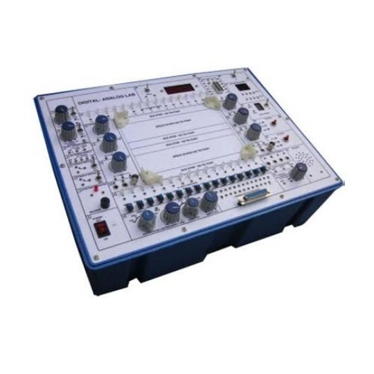
Advanced Digital Logic Lab.
Advanced Digital Logic Lab is designed for students and engineers interested in developing and testing prototype circuits. The lab includes combinational logic, sequential logic, memory, ADC/DAC. experiment circuits and offers several application circuits (PWM, timer, motor control..etc.).
All the necessary equipment for digital logic experiments such as power supply, clock generator, switches, displays are built-in on the main unit. The lab has 10 experiment modules and one CPLD & breadboard experiment module.
Combinational Logic Circuit Experiment
(1) NOR gate circuit
(2) NAND gate circuit
(3) XOR gate circuit
a. Constructing XOR gate with NAND gate
b. The combination with basic gates
(4) AND-OR-INVERTER (A-O-I) gate circuit
(5) Comparator circuit
a. Comparator constructed with basic logic gates
b. Comparator constructed with TTL IC
(6) Schmitt gate circuit
(7) Open-collector gate circuit
a. High voltage / current circuit
b. Constructing an AND gate with open-collector gate
(8) Half-adder and full-adder circuit
Construct HA with basic logic gates
(9) Half-subtractor and full-subtractor circuit
Subtractor circuit constructed with basic logic gates
(10) Bit parity generator circuit
Bit parity generator constructed with XOR gates
(11) Constructing a 4-to-10 decoder with TTL IC
(12) The switch characteristics of TTL level conversion circuit
2. Arithmetical Logic / Tri-state & Code Converter Experiment
(1) CMOS FET tristate gate circuit
a. Truth table measurements
b. Constructing an AND gate with tristate gate
c. Bidirectional transmission circuit
(2) Half-adder and full-adder circuit
a. Full-adder circuit with IC
b. High-speed adder carry generator circuit
c. BCD code adder circuit
(3) Half-subtractor and full-subtractor circuit
Full-adder and inverter circuit
(4) Arithmetic Logic Unit (ALU) circuit
(5) Bit parity generator circuit
Bit parity generator IC
(6) Hex to Dec / Dec to Hex digital conversion
a. 8-digit Dec-to-Hex conversion
b. 8-bit Hex-to-Dec conversion
3. Encoder, Decoder & Multiplexer Logic Circuit Experiment
(1) Encoder circuit
a. Constructing a 4-to-2 encoder with basic gates
b. Constructing a 9-to-4 encoder with TTL IC
(2) Decoder circuit
a. Constructing a 2-to-4 decoder with basic gates
b. BCD-to-7-segment decoder (KL-34003 block d)
(3) Multiplexer circuit
a. Constructing a 2-to-1 multiplexer
b. Using multiplexers to create functions
c. Constructing a 8-to-1 multiplexer circuit with TTL IC
(4) Demultiplexer circuit
Constructing a 2-output demultiplexer with basic logic gates
(5) Digitally controlled analog multiplexer / demultiplexer circuit
(6) The switch characteristics of CMOS level conversion circuit
4. Flip-flop & Sequential Logic & Counter Circuit Experiment
(1) Flip-flop circuits
a. Construct R-S flip-flop with basic logic gates
b. Construct D flip-flop with R-S flip-flops
c. Construct noise elimination circuit with R-S flip-flops
d. Construct J-K flip-flop with D flip-flops
e. The J-K flip-flop of delay and differential
f . Construct master-slave J-K flip-flops with dual R-S flip-flops
g. Construct shift register with D flip-flops
h. Preset left / right shift register
(2) J-K flip-flop counters
a. Asynchronous binary up counter
b. Asynchronous binary down counter
c. Asynchronous decade up counter
d. Synchronous binary counter
e. Synchronous binary up counter
f. Synchronous binary up / down counter
g. Johnson counter
h. Ring counter
5. Oscillator / Pulse ; Load ; Up / Down Counter Circuit Experiment
(1) Constructing Random Access Memory (RAM) with D flip-flop
(2) 64-bit Random Access Memory (RAM) circuit
(3) Erasable Programmable Read Only Memory (EPROM) circuit
(4) Asynchronous four-bit binary up counter (use of 7493 IC)
(5) Presetable binary up/down counter
(6) Presetable decimal up/down counter
(7) Construct Non-retriggerable circuit with the specialized CMOS IC
(8) Construct retriggerable circuit with CMOS IC
(9) Construct a variable duty cycle oscillator circuit with dual monostable multivibrators
6. Memory, Matrix LED & DAC/ADC & MCU Interface Circuit Experiment
(1) Electronic EPROM (EEPROM) circuit
(2) DAC0800 unipolar conversion circuit experiments
(3) Bipolar output conversion circuit
(4) ADC0804 8-bit SAC analog-to-digital converter experiment
(5) Constructing dynamic scanning counter with single chip microprocessor
7. Digital & Analog Timer, Pulse Generator Circuit Experiment
(1) Constructing oscillator circuit with basic logic gates
a. Resistor-capacitor multivibrator
b. Resistor-capacitor crystal multivibrator
(2) Constructing oscillator circuit with schmitt gate
a. Resistor-capacitor oscillator
b. Variable duty cycle resistor-capacitor oscillator
(3) 555 IC oscillator circuit
a. 555 oscillator circuit
b. Voltage controlled oscillator circuit
(4) Monostable multivibrator circuits
a. Low-speed monostable multivibrator circuits
b. Monostable ON/OFF delay circuit
c. Monostable ON/OFF timer circuit
d. Construct monostable multivibrator circuit with 555 IC
(5) Numerically-Controlled Oscillator (NCO) signal generator
(6) Precise-frequency function generator
(7) Variable-duty-cycle NCO signal generator
(8) Variable-ON/OFF delay and difference control experiments
(9) Precise 15-bit symmetric / asymmetric PWM generator
8. Ramp-compare / SAR / Dual-slope ADC Experiment
(1) Simple R-2R unipolar output D/A converter experiments
(2) 8-bit digital-ramp A/D converter experiment
(3) 8-bit successive-approximation A/D converter experiment
(4) 8-bit dual-slope A/D converter experiment
9. Keyboard & Display For Stepping Motor Position Control
(1) Stepper motor position / speed control experiment
10. Precise Digital Clock Timer
(1) Clock experiment
(2) Timer experiment
11. Universal CPLD & Breadboard Experiment
(1) Create block diagram / schematic file in QUARTUS II
(2) 16-bit Hex counter
(3) 16-bit decimal counter
(4) 16-bit presetable decimal up / down counter
(5) 16-bit scanning controller for 7-segment display
(6) 16-bit up / down counter and its indication by a 7-segment display
(7) Electronic music box
(8) The traffic light with animation and time indication