 lab@motestainstruments.com | Civil and Mechanical Engineering Lab Equipments India China

Code: NAE0031
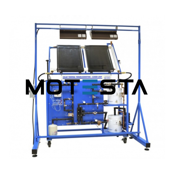
Solar Thermal Troubleshooting Systems.
Solar Thermal Troubleshooting Systems Supply and Consumption at 12 V (DC).
Supply and Consumption in alternating current (AC).
Supply to the network (grid).
Solar Panel (polycrystalline) mounted on an anodized aluminum structure with wheels for mobility, and with calibrated cell to measure solar irradiation. Should consist of 36 high performance photovoltaic cells (35 x 55 mm), with a typical power of 50Wp for a 17Vdc voltage.
Technical data:
Maximum nominal power: 66W. Voltage at maximum power point (Vmpp): 17.8 V. Current at maximum power point (Impp): 3.70 A. Short-circuit current (Isc): 4.05 A. Open circuit voltage (Voc): 22.25 V. Dimensions: 660 x 35.5 x 780 mm. Weight: 3 Kg. approx.
Battery offering optimal performance with low power applications. Set of interconnection cables. Rack for modules allocation.
Solar charge controller with an automatic recognition for operating voltage 12 V or 24 V. It
should monitor several parameters such as voltage, current and charge level of the battery, load current, status, etc. Additional functions should be activated such as the settings, night light function and auto-test. The regulator should be equipped with various devices to protect its electronics, battery and load. Loads should incorporate two 12 V, 20W lamps, with independent switches. DC/AC inverter that outputs a sine wave shaped output of 230V/50Hz ± 2% and the nominal input voltage is 12Vdc. Two different operating modes: continuous mode and ASB mode (Auto Standby) to reduce the power consumption. It should also be able to provide the user with adiagnosis system to indicate to the user the status by different flash sequences.
AC Voltage measurements module until 250V. and DC until 250 V (digital multimeter).
Module for measurements of solar irradiation (W/m2) and measurements of current until 10A, with digital multimeter.
Module for 12Vdc battery charger.
Grid Connection Inverter Kit.
Inverter used for the conversion and injection to the grid of the power generated by a simulated source of renewable energy.
The operation mode should be displayed by means of an indicating LED at the front side of the housing.
Grid Connection Inverter
Input (DC): Nominal power @ 25ºC: 150 W. Maximum power @ 25ºC: 220 W.
MPP voltage: 45-125V DC. Maximum voltage: 155V DC. Nominal current: 3A.
Output (AC): Voltage: 230V (207 - 253 V). Maximum power, fuse: 2A.
Frequency: 50 Hz (49.8 ~ 50.2 Hz).
EXERCISES AND PRACTICAL POSSIBILITIES
1. Determination of the constituent material of the solar cell.
2. Determination of the I-V first quadrant curve without illuminating the solar cell.
3. Determination of the inverse (or saturation) current of the cell without illumination.
4. Determination of parallel and series resistance of a solar cell without illumination.
5. Dependency of the open circuit voltage (Voc) with lumens (luminous flux).
6. Determination of the parameters that describe the quality of a solar cell.
7. Solar energy measurement.
8. Measurement of the solar panel voltage with no load.
9. Determination of the disposition of cells in a solar panel.
10. Familiarisation with the regulator parameters.
11. Loads connection to 12 Volts DC.
12. Loads connection to 220 Volts AC.
13. Study of the grid utility inverter.
14. Battery charging.
NB: (Installation and Training, required)